
Using CubeIDE create PWM waves on Nucleo F411RE Board
Published:
Background
One of my current project is to create a compact version of device taht consists of a STM32 MCU, a PIR sensor, a Bluetooth module, a temperature/humidity sensor, and a LC driver.
For a LC driver, the electrical schematic is looks like this
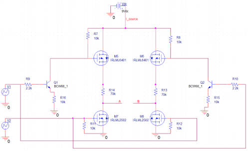 .
.
The purpose of this circuit is to provide the liquid crystal cell an alternative current waveform of around 100 Hz. The amplitude of the AC signal depends on the Vdc (source). The ideal input and output waveform is like this:
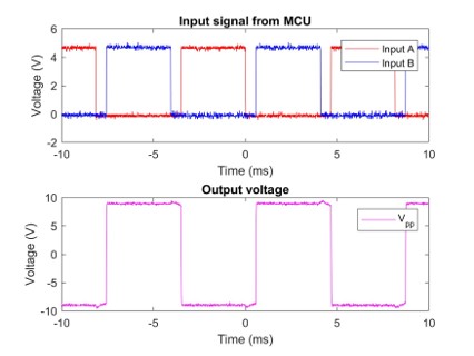 .
.
The input to the LC driver circuit is two out of phase PWM waveform. The duty cycle of both PWM is the same and less than 50%. The reason is to eliminate the case when both PWM is in HIGH level, which is burn the circuit!
This Blog
This blog it to show how to use CubeIDE (which is an Eclipse distribution for ARM MCU devemopment) to deploy two out-of-phase PWM waveforms by change setting of TIMER.
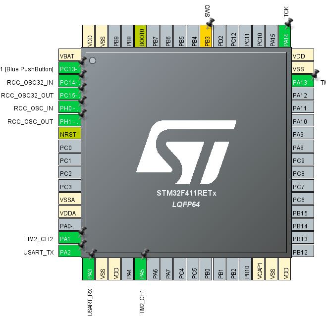
Firstly, open CubeMX software, create “new project” and select the board “Nucleo F411RE”. After initialization, we set two PINs to be our desired PWM channel. Here, we select PA5 and PA1, which is TIM2_CH1 and TIM2_CH2, respectively. We only use one TIMER to save resource.
Go to Clock Configuration panel and set the clock to be HCLK=8MHZ. Then, APB1 periperal clock is 4MHz.
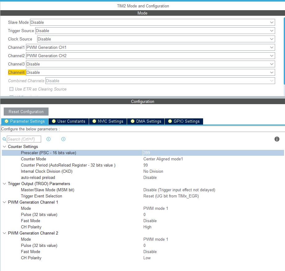
Then selectim TIM2 in the left bar to configure the TIM2 settings.
- Select “PWM Generation CH1/2” in Channel 1/2.
- Set Prescalar to 399. This number makes the clock for the TIMER2 is 4MHz/(399+1)=10kHz, which means 100us.
- Set counter mode to be “Center Aligned Mode 1”. This will make the center of two channel align to each other, rather than edge aligned.
- Counter Period set to 99. This means that TIMER2 will take 100us(99 + 1) = 10ms, which is 100Hz. In a word, the PWM’s frequency related to the system clock, prescalar and period. PWM frequence = F_sys/(PrescalarPeriod).
- Set CH Polarity of Channel 1 and 2 to be High and Low, respectively. This is to make sure Channel 2 will be outof phase.
Next, generate code and open project in CubeIDE.
Check the generated code has the TIM2_Init().
static void MX_TIM2_Init(void)
{

  /* USER CODE BEGIN TIM2_Init 0 */

  /* USER CODE END TIM2_Init 0 */

  TIM_MasterConfigTypeDef sMasterConfig = {0};
  TIM_OC_InitTypeDef sConfigOC = {0};

  /* USER CODE BEGIN TIM2_Init 1 */

  /* USER CODE END TIM2_Init 1 */
  htim2.Instance = TIM2;
  htim2.Init.Prescaler = 399;
  htim2.Init.CounterMode = TIM_COUNTERMODE_CENTERALIGNED1;
  htim2.Init.Period = 99;
  htim2.Init.ClockDivision = TIM_CLOCKDIVISION_DIV1;
  htim2.Init.AutoReloadPreload = TIM_AUTORELOAD_PRELOAD_DISABLE;
  if (HAL_TIM_PWM_Init(&htim2) != HAL_OK)
  {
    Error_Handler();
  }
  sMasterConfig.MasterOutputTrigger = TIM_TRGO_RESET;
  sMasterConfig.MasterSlaveMode = TIM_MASTERSLAVEMODE_DISABLE;
  if (HAL_TIMEx_MasterConfigSynchronization(&htim2, &sMasterConfig) != HAL_OK)
  {
    Error_Handler();
  }
  sConfigOC.OCMode = TIM_OCMODE_PWM1;
  sConfigOC.Pulse = 0;
  sConfigOC.OCPolarity = TIM_OCPOLARITY_HIGH;
  sConfigOC.OCFastMode = TIM_OCFAST_DISABLE;
  if (HAL_TIM_PWM_ConfigChannel(&htim2, &sConfigOC, TIM_CHANNEL_1) != HAL_OK)
  {
    Error_Handler();
  }
  sConfigOC.OCPolarity = TIM_OCPOLARITY_LOW;
  if (HAL_TIM_PWM_ConfigChannel(&htim2, &sConfigOC, TIM_CHANNEL_2) != HAL_OK)
  {
    Error_Handler();
  }
  /* USER CODE BEGIN TIM2_Init 2 */

  /* USER CODE END TIM2_Init 2 */
  HAL_TIM_MspPostInit(&htim2);

}
In main(), insert the following code
  /* USER CODE BEGIN 2 */
  HAL_TIM_PWM_Start(&htim2, TIM_CHANNEL_1);		//start TIM2_CH1
  HAL_TIM_PWM_Start(&htim2, TIM_CHANNEL_2);		//start TIM2_CH2
  /* USER CODE END 2 */

  /* Infinite loop */
  /* USER CODE BEGIN WHILE */
  while (1)
  {
    /* USER CODE END WHILE */
	  pwm1 = 40;	//determine the duty cycle, pwm1/period = 0.4
	  pwm2 = 60;	//determine the duty cycle, 1-pwm2/period = 0.4, because polarity is LOW.
	  __HAL_TIM_SET_COMPARE(&htim2, TIM_CHANNEL_1, pwm1);	// compare counter with pwm1
	  __HAL_TIM_SET_COMPARE(&htim2, TIM_CHANNEL_2, pwm2);	// compare counter with pwm2
    /* USER CODE BEGIN 3 */
    /* USER CODE BEGIN 3 */
  }
  /* USER CODE END 3 */
}
Build and debug.
The waveform of the two PIN is shown like this, captured by an logic analyzer:
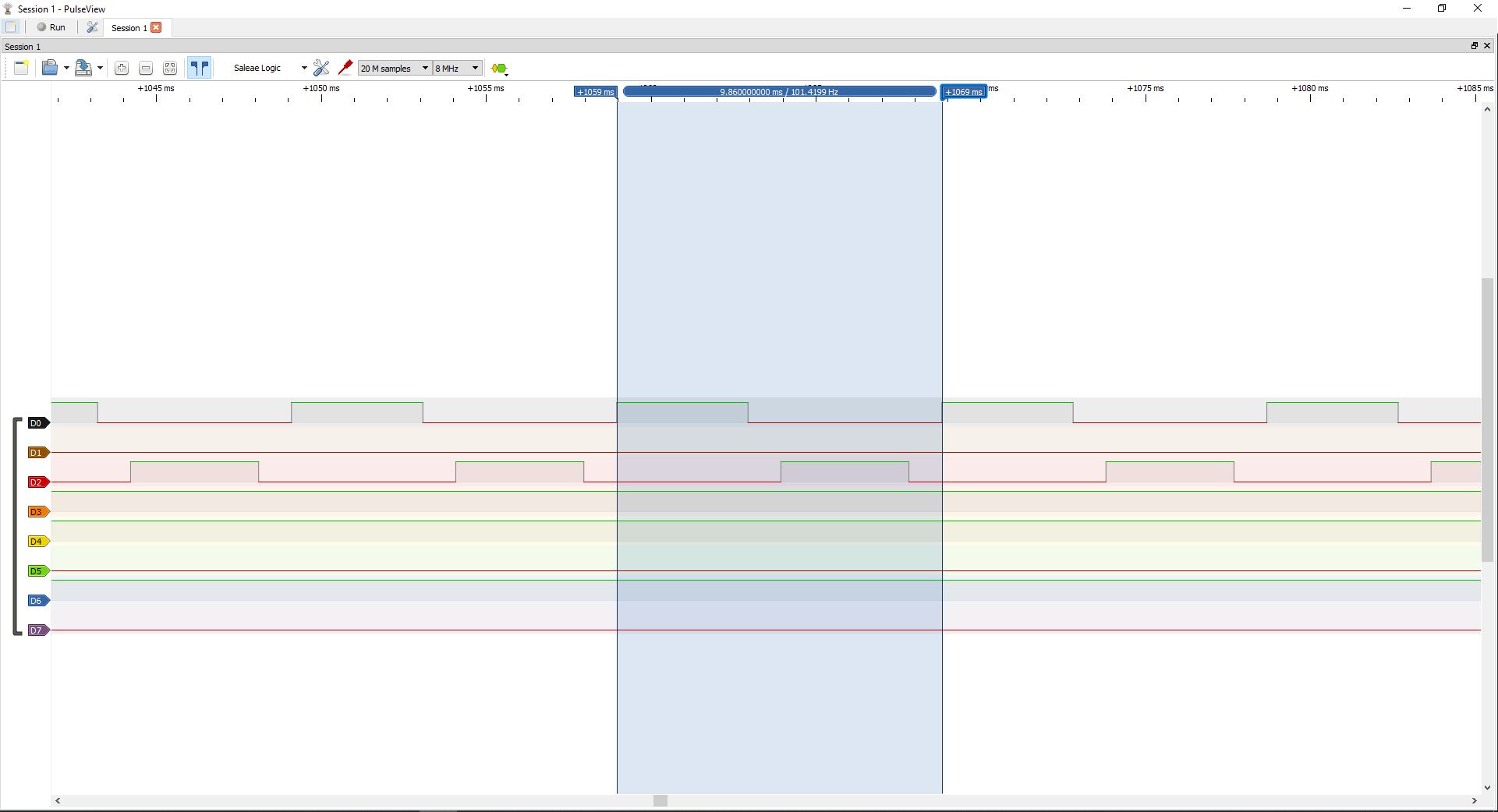
The frequency of both PWM channel is around 100Hz, duty cycle is 40% and out of phase.
Update 10-04-2019
I try the same thing on STM32L432KC Nucleo board. The function works fine, but one issue is about clock.
I already configure the APB1 clock to be 4MHz. And set PWM prescalar to be 399, period to be 99. Thus, the actual PWM period is 4MHz/400/100 = 100Hz. But the logic annlyzer shows a 50Hz period. This is weird…